Bilješka
Pristup ovoj stranici zahtijeva provjeru vjerodostojnosti. Možete pokušati da se prijavite ili promijenite direktorije.
Pristup ovoj stranici zahtijeva provjeru vjerodostojnosti. Možete pokušati promijeniti direktorije.
This article describes the network reference pattern for disaggregated Azure Local clusters that use Internet Small Computer Systems Interface (iSCSI) Storage Area Network (SAN) external storage with the 6-NIC dedicated-path model. In this model, dedicated standalone adapters carry iSCSI storage traffic.
For an overview of the leaf-spine fabric architecture, traffic flow, and key concepts such as Virtual Routing and Forwarding (VRF), Virtual Extensible LAN (VXLAN), and the role of compute leaf switches vs. service leaf switches, see Network reference patterns overview for disaggregated deployments.
When to use this pattern
Use this pattern when your deployment meets the following criteria:
- Storage is provided by an external iSCSI SAN.
- You want dedicated Ethernet adapters for iSCSI path A and iSCSI path B.
- You want the option to add an in-guest backup network for guest VMs after deployment.
- The cluster spans one or more racks with up to 64 nodes.
Architecture overview
This pattern uses a leaf-spine (Clos) topology with the following components:
- Leaf switches (Top of Rack) in each rack for server connectivity.
- Spine switches for cross-rack transit.
- Service leaf switches for data center core peering, route leaking, and service appliance integration.
- iSCSI storage array reachable through redundant dedicated iSCSI paths.

For detailed information about how the underlay, overlay, and Virtual Routing and Forwarding (VRF) segmentation work together, see How the fabric works.
VLAN to VXLAN Network Identifier (VNI) mapping
Place all VXLAN Network Identifiers (VNIs) inside the cluster Virtual Routing and Forwarding (VRF) to maintain traffic isolation. Each VLAN maps to a unique VNI, and this mapping is consistent across all racks. The following table shows an example configuration for disaggregated deployments spanning multiple racks.
| VLAN | Name | VNI | Purpose |
|---|---|---|---|
| 7 | Azure Local infrastructure subnet | 10007 | VLAN configured in access mode on the leaf for Azure Local management. |
| 1711 | Cluster subnet 1 | 11711 | VLAN configured in access mode on the leaf for cluster network 1. |
| 1712 | Cluster subnet 2 | 11712 | VLAN configured in access mode on the leaf for cluster network 2. |
| 300 | iSCSI path A | 10300 | VLAN configured for dedicated iSCSI storage path A. |
| 400 | iSCSI path B | 10400 | VLAN configured for dedicated iSCSI storage path B. |
| 800 | Backup subnet | 10800 | Optional VLAN configured in trunk mode on the management and compute intent for in-guest backup traffic. Add this VLAN only if you manually configure a backup host vNIC after deployment. |
| 100 | Tenant 1 | 10100 | VLAN configured in trunk mode on the leaf for Tenant 1 logical network (LNET) virtual machine traffic. |
| 200 | Tenant 2 | 10200 | VLAN configured in trunk mode on the leaf for Tenant 2 logical network (LNET) virtual machine traffic. |
Leaf and spine fabric requirements
For the full list of switch capabilities required for leaf-spine Clos deployments, including underlay, overlay, segmentation, Quality of Service (QoS), high availability, and scale requirements, see Leaf and spine fabric requirements.
Host NIC configuration
Each server node connects to the network through six Ethernet network adapter ports across three dual-port network adapters.
In this pattern:
- Use two network adapter ports for the management and compute intent.
- Use two network adapter ports for the cluster networks.
- Use two network adapter ports for dedicated iSCSI SAN connectivity.
If you require an in-guest backup network for guest VMs, use the existing management and compute intent that Network ATC creates on the first network adapter (NIC1 and NIC2). After deployment completes and the management and compute intent is created, you can manually add a backup host vNIC to the Network ATC-managed SET switch and trunk the backup VLAN on the management and compute ports. The cluster networks on NIC3 and NIC4 remain dedicated to CSV, live migration, and cluster heartbeat traffic, and NIC5 and NIC6 remain dedicated standalone iSCSI path A and path B.
Note
For any iSCSI pattern, the storage network adapters must support a minimum speed of 10 GbE. Use a higher speed, such as 25 GbE or greater, for high-throughput workloads.
Baseboard Management Controller (BMC) network adapter
Each server also has a Baseboard Management Controller (BMC) network port for out-of-band management. BMC traffic doesn't go through the leaf switches. BMC switches connect to the service leaf pair, keeping out-of-band management on a dedicated path through the fabric. This design ensures that a leaf failure doesn't affect your ability to remotely manage servers, and BMC traffic is isolated from compute and storage workloads. BMC devices can be accessed via a Layer 3 network, and access can be controlled through firewall services.
Port allocation per compute leaf switch
The following table shows the host network port allocation per compute leaf physical switch. Each rack has 16 nodes:
| Port range | Function | Leaf A VLANs | Leaf B VLANs | Notes |
|---|---|---|---|---|
| 1-16 | Management and compute ports | VLAN 7 for management. VLANs 100 and 200 for tenants. | VLAN 7 for management. VLANs 100 and 200 for tenants. | Native VLAN 7 in access mode. VLANs 100 and 200 for tenants in trunk mode. If you add a backup host vNIC after deployment, trunk VLAN 800 on these ports. |
| 17-32 | Cluster network ports | VLAN 1711 for cluster network 1. | VLAN 1712 for cluster network 2. | Second network adapter ports for dedicated cluster traffic (CSV, live migration, and cluster heartbeat). |
| 33-48 | Dedicated iSCSI ports | VLAN 300 for iSCSI path A. | VLAN 400 for iSCSI path B. | Third network adapter ports for dedicated iSCSI storage paths. |
| 49 | Internal BGP (iBGP) peering between leaf switches | N/A | N/A | Layer 3 routing. |
| 50 | Reserved | N/A | N/A | N/A |
| 51-52 | External BGP (eBGP) uplinks to spine switches | N/A | N/A | Layer 3 routing. |
| 53-56 | Reserved | N/A | N/A | N/A |
iSCSI dedicated storage paths
Each server has two dedicated standalone physical paths for iSCSI traffic:
- NIC5 connects to leaf A and carries iSCSI path A.
- NIC6 connects to leaf B and carries iSCSI path B.
The following diagram shows a logical representation of how the host networking and iSCSI dedicated paths are configured in this pattern:
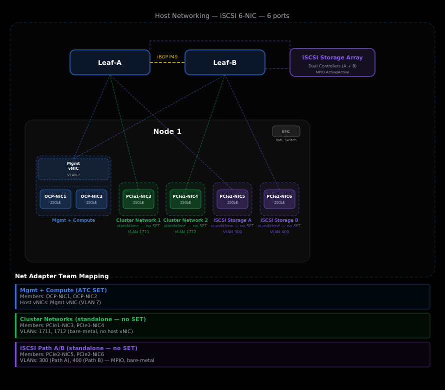
Network ATC intents
In the iSCSI 6-NIC model, Network ATC manages the management and compute intent. iSCSI storage paths use dedicated standalone network ports and aren't managed by Network ATC.
- Management and compute intent - Switch Embedded Teaming (SET) switch with the management virtual network interface.
- Cluster network 1 - Cluster traffic on NIC3.
- Cluster network 2 - Cluster traffic on NIC4.
- iSCSI path A - Dedicated standalone NIC5.
- iSCSI path B - Dedicated standalone NIC6.
Note
To provide an in-guest backup network, manually add a backup host vNIC to the Network ATC-managed management and compute intent after deployment. The cluster and iSCSI adapters remain unchanged on their dedicated paths.
Quality of Service (QoS) settings
Because iSCSI storage traffic uses dedicated adapters, the host adapter separates cluster and storage traffic. Configure jumbo frames (MTU 9000 on the host and MTU 9216 on the switch) and multipathing as part of the validated iSCSI design.
When you use iSCSI as the storage backend, it replaces Storage Spaces Direct (S2D) and removes Remote Direct Memory Access (RDMA) from the design. Because all traffic, including iSCSI, CSV, live migration, and cluster heartbeat, runs over TCP, lossless Ethernet isn't required. Priority Flow Control (PFC) is disabled and no pause frames are used.
This pattern doesn't use Enhanced Transmission Selection (ETS) bandwidth reservations. In a leaf-spine (Clos) fabric, the cluster spans multiple racks and traffic crosses Layer 3 (routed) boundaries between leaf and spine switches. The 802.1p Class of Service (CoS) tags that ETS relies on are Layer 2 constructs that don't survive a Layer 3 hop, so ETS bandwidth guarantees can't be enforced end-to-end across racks. Configuring ETS would provide protection only within a single rack, which creates an inconsistent and misleading QoS design across the fabric.
Instead, this pattern recommends configuring the host-facing switch ports in access mode (untagged) on the appropriate VLAN for each dedicated adapter. Because each traffic type - management, cluster, iSCSI path A, and iSCSI path B - uses its own dedicated adapter and subnet, there's no need to trunk multiple VLANs or classify and prioritize traffic on a shared link. Physical separation across dedicated adapters provides the traffic isolation that ETS would otherwise attempt to enforce on a shared link.
Note
Apply matching jumbo frame and multipathing settings on the host and switch. Follow your storage vendor guidance for any additional Data Center Bridging (DCB) requirements as part of the validated end-to-end design.
iSCSI host static routes
Each host node has multiple network interfaces on different subnets. Only the management interface has a default gateway. Assign IP addresses without a default gateway to the cluster and iSCSI interfaces.
To reach iSCSI targets that are one or more Layer 3 hops away, you must configure a persistent static route on each host node for every iSCSI target IP. Without a static route, the host has no valid path to the iSCSI target through the storage interface, and traffic is either dropped or incorrectly routed through the management default gateway. Incorrect routing breaks storage isolation and can cause performance or stability issues.
Static routes ensure that iSCSI traffic always exits the storage network adapter, uses the storage VLAN and leaf switch gateway, and never traverses the management network.
Example: host with a single iSCSI target
In the 6-NIC model, iSCSI path A and path B use dedicated standalone adapters on separate VLANs and subnets. The following table shows an example of the host interfaces:
| Interface | IP address | Subnet | Gateway | Role |
|---|---|---|---|---|
| Management (NIC1) | 192.168.1.10 | /24 | 192.168.1.1 | Default gateway. All non-specific traffic exits here. |
| Cluster network 1 (NIC3) | 10.10.100.50 | /24 | None | CSV and live migration. Local cluster traffic only. |
| Cluster network 2 (NIC4) | 10.10.101.50 | /24 | None | CSV and live migration. Local cluster traffic only. |
| iSCSI path A (NIC5) | 10.30.30.10 | /24 | None | Dedicated storage path A. Reaches iSCSI targets through a static route. |
| iSCSI path B (NIC6) | 10.31.31.10 | /24 | None | Dedicated storage path B. Reaches iSCSI targets through a static route. |
For each iSCSI target on a remote subnet multiple Layer 3 hops away, configure a persistent static route that directs target traffic through the storage network adapter. The following table explains each route component:
| Route component | Value | Explanation |
|---|---|---|
| Destination | A /32 host route for each iSCSI target IP | One route per iSCSI target IP. |
| Next hop | Leaf switch SVI (gateway) on the iSCSI VLAN | Directs storage traffic to the iSCSI fabric gateway. |
| Interface | The iSCSI storage network adapter (NIC5 or NIC6) | Forces traffic out the storage network adapter, not management. |
Multiple iSCSI targets and Multipath I/O (MPIO)
If the iSCSI array exposes multiple target IPs, such as different controllers or LUN paths, configure one /32 static route per target IP on each host for each applicable iSCSI network adapter. In a Multipath I/O (MPIO) configuration, each iSCSI path requires its own static route to the same targets, using the gateway on its respective VLAN. This approach ensures deterministic path selection, proper MPIO load balancing and failover, and no leakage of storage traffic into the management or cluster networks.
Tip
If an array exposes many target IPs within the same subnet, you can configure one route to the target subnet instead of one /32 route per target IP. For example, route the entire iSCSI path A target subnet through the path A gateway and the path B target subnet through the path B gateway. This approach reduces the number of routes while keeping storage traffic on the correct adapter.
Configure the iSCSI initiator, static routes, and MPIO
After you plan the storage IP addressing and routing, configure the iSCSI initiator on each host node as part of operating system installation. This configuration includes assigning IP addresses to the storage adapters, disabling DNS registration, adding persistent static routes, enabling the Microsoft iSCSI Initiator service (MSiSCSI), enabling Multipath I/O (MPIO) automatic claim for the iSCSI bus type, and connecting persistent multipath sessions to each target portal.
For the step-by-step commands, see the iSCSI tab in Install the Azure Local operating system for disaggregated deployments.
Workload placement considerations
In a multirack Clos fabric, the physical location of workloads affects traffic patterns and bandwidth requirements. While the leaf-spine topology provides equal-cost paths between any two racks, workload placement can create uneven traffic distribution that impacts performance.
Key considerations:
- High east-west traffic workloads - Colocating these workloads on the same rack or adjacent racks reduces spine bandwidth consumption.
- Storage-heavy workloads - Validate that the dedicated iSCSI adapters and storage fabric provide sufficient bandwidth for your storage requirements.
- Power-dense racks - These racks might require spreading workloads across racks for thermal or power distribution reasons, which increases cross-rack traffic.
- Backup traffic - If you add a backup host vNIC, VMs send backup traffic over the backup VLAN trunked on the management and compute intent. Scheduling backup windows and co-locating backup-intensive VMs can reduce cross-rack backup traffic on spine links.
Note
Azure Local doesn't currently provide hard workload placement controls (rack affinity). Administrators should be aware that uneven workload distribution might require adjusting the spine-to-leaf bandwidth ratio or adding spine capacity.