Bilješka
Pristup ovoj stranici zahtijeva provjeru vjerodostojnosti. Možete pokušati da se prijavite ili promijenite direktorije.
Pristup ovoj stranici zahtijeva provjeru vjerodostojnosti. Možete pokušati promijeniti direktorije.
This article provides an overview of network reference patterns for disaggregated deployments of Azure Local. Use this guide to understand the leaf-spine fabric architecture, how traffic flows between racks, and how external connectivity is managed through service leaf switches.
What is a disaggregated deployment?
In a disaggregated deployment, compute and storage are separated. Storage is provided by an external Storage Area Network (SAN), such as Fiber Channel (FC) or iSCSI, instead of local disks inside each server node. This separation allows compute, storage, and network to scale independently - add racks with their own leaf switch pairs for more compute, expand the SAN for more storage, or add spine switches for more cross-rack bandwidth.
A disaggregated deployment consists of single-node or multinode systems (up to 64 nodes per cluster) with the following characteristics:
Note
Not all disaggregated deployments span multiple racks. If the disaggregated cluster remains single-rack and doesn't require SDN at scale, you can use the simpler single-rack topology with a two-switch HSRP pair.
- At least two service leaf network switches for external connectivity.
- At least two spine network switches for cross-rack transit.
- At least two leaf (Top of Rack) network switches per rack.
- At least four network adapter ports per server - two ports for the management and compute intent, and two ports for the cluster networks. In disaggregated deployments, the cluster networks use standalone ports without a Network ATC intent and are automatically configured during deployment.
- In Fiber Channel (FC) SAN configurations, storage traffic runs entirely on the FC fabric, separate from the Ethernet network.
- In iSCSI SAN configurations, storage traffic runs over dedicated Ethernet adapters and a dedicated iSCSI storage fabric.
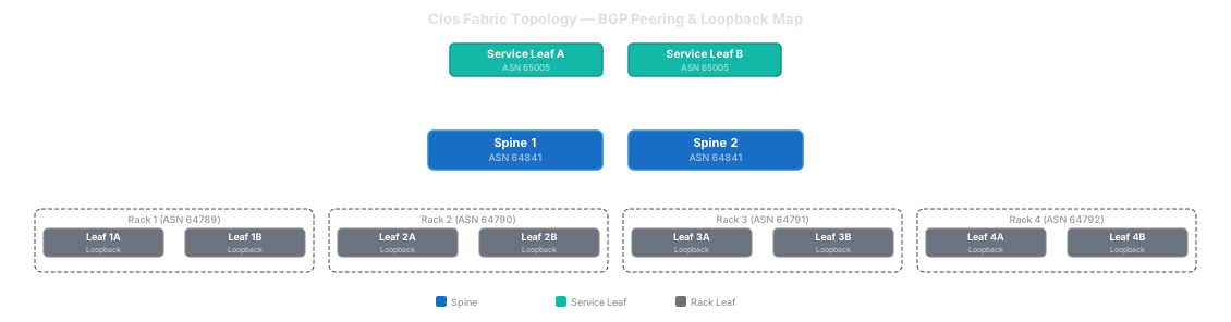
Supported disaggregated network reference patterns
The following network reference patterns are available for disaggregated deployments:
| Storage connectivity | Backup network | Reference pattern |
|---|---|---|
| Fiber Channel SAN | No dedicated backup network | Fiber Channel disaggregated pattern without backup network |
| Fiber Channel SAN | Dedicated backup network | Fiber Channel disaggregated pattern with backup network |
| iSCSI SAN | Optional in-guest backup network (added after deployment) | iSCSI 6-NIC disaggregated pattern |
Why use a leaf-spine (Clos) topology?
A traditional two-switch design (one pair of Top of Rack switches) works for small clusters but doesn't scale well. At 64 nodes across multiple racks:
- Port limits - A single Top of Rack (TOR) switch has about 48 ports and can't connect 64 or more nodes.
- Failure impact - If one switch fails, half your cluster loses connectivity.
- Bandwidth bottleneck - All cross-rack traffic funnels through a single pair of uplinks.
A leaf-spine (Clos) topology solves these problems by adding a dedicated spine layer that interconnects all racks. Every rack gets its own pair of leaf switches. All leaf switches connect to the shared spine switches. Traffic between racks follows: Leaf → Spine → Leaf - never more than three hops.
Think of it like a highway system:
| Network concept | Highway analogy |
|---|---|
| Leaf switches (Top of Rack) | Local roads that connect directly to your house (servers). |
| Spine switches | Highway interchanges that connect all the local roads together. |
| Nodes | Houses where people (workloads) live. |
| Virtual Routing and Forwarding (VRF) | Separate highway systems that don't share exits (traffic isolation). |
| Virtual Extensible LAN (VXLAN) | Tunnels that let local roads extend across highway systems. |
| Service leaf | The border checkpoint where traffic enters or exits the highway system. |
Oversubscription
The leaf-to-spine layer is designed for a minimum 2:1 oversubscription ratio (leaf downlink bandwidth to leaf-to-spine uplink bandwidth) under normal operations.
Tip
What is oversubscription? A 2:1 ratio means the total server-facing bandwidth on each leaf is twice the bandwidth of the uplinks to the spines. For example, if a leaf has 48 × 25-GbE host ports (1,200 Gbps total) and 4 × 100-GbE spine uplinks (400 Gbps), the ratio is 3:1. Under normal conditions, not all servers transmit at full rate simultaneously, so moderate oversubscription is acceptable.
During a spine failure or maintenance window, the effective oversubscription can increase to 4:1. During this period, workloads with heavy east-west (cross-rack) traffic might experience reduced throughput until full spine capacity is restored.
To reduce congestion risk and improve resiliency, scale the spine layer horizontally as the environment grows. Adding spine switches increases aggregate leaf-to-spine bandwidth and adds more Equal-Cost Multipath (ECMP) paths, improving both performance and fault tolerance.
How the fabric works
The leaf-spine fabric is built on three layers: the underlay for routing between switches, the overlay for extending VLANs across racks, and Virtual Routing and Forwarding (VRF) segmentation for isolating traffic types.
Underlay - eBGP routing between switches
The underlay is the routed Layer 3 network that connects all leaf and spine switches. It uses external Border Gateway Protocol (eBGP) with unnumbered interfaces (RFC 5549), meaning each switch-to-switch link uses IPv6 link-local addresses for BGP peering rather than manually assigned /30 or /31 subnets. Each rack gets a unique BGP Autonomous System Number (ASN). Equal-Cost Multipath (ECMP) distributes traffic across all available spine paths.
Note
BGP unnumbered is the recommended option, but using /31 point-to-point subnets is also supported. Choose either method based on your operational preferences.
The underlay runs in the default Virtual Routing and Forwarding (VRF) instance (the global routing table), but it's treated as infrastructure-only - it carries only loopback addresses and BGP peer routes. No default route (0.0.0.0/0) is injected into the underlay, and no workload prefixes are leaked into it. All workload traffic is isolated in dedicated overlay VRFs, each mapped to its own VXLAN Network Identifier (VNI). The underlay never sees tenant or cluster IP addresses - they're encapsulated inside VXLAN tunnels before entering the fabric.
This separation is the critical security boundary. If a misconfiguration or rogue route advertisement occurs in one overlay VRF, it can't affect the underlay or other VRFs - they're fundamentally separated by VXLAN encapsulation.
Overlay - VXLAN EVPN for extending VLANs across racks
Azure Local requires certain VLANs, such as management and compute, to be available on every rack. Since VLANs are Layer 2 segments that traditionally can't span routed boundaries, Virtual Extensible LAN (VXLAN) solves this by wrapping Layer 2 frames inside Layer 3 packets. Each VLAN maps to a unique VXLAN Network Identifier (VNI), and this mapping is consistent across all racks.
Ethernet Virtual Private Network (EVPN) is the BGP-based control plane that tells every switch where each MAC and IP address lives - without flooding the network.
Segmentation - VRFs for traffic isolation
Virtual Routing and Forwarding (VRF) instances create isolated routing domains on each switch - like having multiple invisible switches sharing the same hardware. Different traffic types - management, compute/cluster, tenant workloads - are placed into separate VRFs so that a routing mistake in one domain doesn't affect the others.

Note
Each cluster can be placed in its own VRF, depending on your isolation requirements. This enables multitenancy without additional hardware.
Compute leaf vs. service leaf
Not all leaf switches have the same role. The fabric has two types of leaf switches with distinct responsibilities:
| Function | Compute leaf | Service leaf |
|---|---|---|
| Virtual Extensible LAN (VXLAN) termination for local servers | Yes | Yes |
| Anycast gateway for workload VLANs | Yes | Yes |
| Spine uplinks | Yes | Yes |
| Data center core peering (external BGP) | No | Yes |
| Route leaking between VRFs | No | Yes |
| Firewall / load balancer attachment | No | Yes |
Compute leaf switches
Compute leaf switches are the host edge. They terminate Virtual Extensible LAN (VXLAN) for locally attached servers, provide anycast gateways for the cluster's workload Virtual Routing and Forwarding (VRF) instances, and participate in the fabric underlay. They do not connect to the data center core and do not perform route leaking to external networks.
Service leaf switches
The service leaf pair is the dedicated boundary between the cluster fabric and the data center core network. Because the service leaf pair participates in multiple Virtual Routing and Forwarding (VRF) instances, it is the natural integration point for:
- Route leaking - controlled import of routes between VRFs for north-south traffic.
- Firewalls and load balancers - connected directly to service leaf ports as service appliances.
- VXLAN termination - wrapping and unwrapping overlay traffic for external connectivity.
Important
The data center core network (upstream routers, firewalls, internet) does not connect directly to the spine switches. All external connectivity is centralized at the service leaf pair. This keeps the spine layer as pure transit with no external dependencies.
Centralizing external connectivity at the service leaf provides the following benefits:
- Spine stability - Core network maintenance (firewall upgrades, router replacements) doesn't affect the spine fabric.
- Simple changes - You can add or remove external connectivity without modifying the spine configuration.
- Reduced blast radius - A routing or policy misconfiguration on the service leaf only affects external connectivity, not the internal fabric.

SDN considerations for disaggregated deployments
Software Defined Networking (SDN) support varies depending on the Azure Local architecture and deployment type. In disaggregated deployments, SDN logical networks (LNETs) are supported through external SDN infrastructure rather than the Microsoft SDN stack.
The following table summarizes SDN support across Azure Local architectures as of version 2604:
| Azure Local architecture | Azure Local version | Number of nodes | SDN supported configuration |
|---|---|---|---|
| Hyperconverged | 2604 | 1 to 16 | Microsoft SDN LNETs and NSGs |
| Hyperconverged hybrid (S2D + SAN attach) | 2604 | 1 to 16 | Microsoft SDN LNETs and NSGs |
| Disaggregated | 2604 | 1 to 64 | External SDN LNETs supported. |
Note
For disaggregated deployments, SDN logical networks must be configured on the external network fabric (leaf-spine switches) rather than through the Microsoft SDN Network Controller. Plan your VXLAN EVPN overlay design accordingly to support the required logical networks.
AKS logical network routing and VRF design
When you create logical networks (LNETs) for Azure Kubernetes Service (AKS) on Azure Local, the AKS LNET must have Layer 3 reachability (line of sight) to the cluster nodes running on the management LNET. AKS uses this path to communicate with the Kubernetes API server and other infrastructure services hosted on the management network. If the AKS LNET can't reach the management LNET, AKS deployment and operations fail. This requirement is specific to AKS—virtual machine (VM) LNETs don't require reachability to the management network.
Option 1: Single VRF
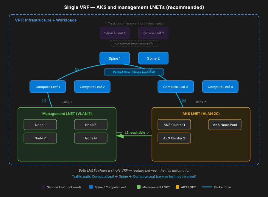
For Azure Local version 2604, one approach is to place both the infrastructure LNETs (management, compute) and the AKS LNETs in a single VRF on the leaf-spine fabric. A single VRF ensures that all LNETs share the same routing table, so reachability between management and AKS networks is automatic—no additional configuration is needed.
With VXLAN EVPN symmetric IRB, inter-subnet traffic between AKS and management LNETs in the same VRF is routed locally at the compute leaf (VTEP) level. Packets traverse Compute Leaf → Spine → Compute Leaf (3 hops). The service leaf switches aren't involved in this east-west traffic, which results in optimal latency and avoids creating a bottleneck at the service leaf tier.
Option 2: Separate VRFs with route leaking
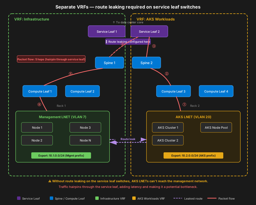
If your environment requires separate VRFs for different workloads or tenants—for example, to meet regulatory isolation requirements—you must configure route leaking on the service leaf switches to allow the necessary traffic between VRFs. At a minimum, the VRF hosting the AKS LNET must import the management LNET prefixes, and the management VRF must import the AKS LNET prefixes. Without these leaked routes, cross-VRF communication fails and AKS can't reach infrastructure services.
Because route leaking is configured on the service leaf switches, cross-VRF traffic must hairpin through the service leaf tier. The packet path becomes Compute Leaf → Spine → Service Leaf → Spine → Compute Leaf (5 hops) instead of the 3-hop path in a single VRF. This extra traversal adds latency and makes the service leaf switches a potential throughput bottleneck for all AKS-to-management communication.
Important
Route leaking introduces shared reachability between otherwise isolated VRFs. Only leak the specific prefixes required for AKS-to-management communication. Avoid leaking default routes or broad summaries, as this action undermines the isolation benefits of separate VRFs.
Same-rack traffic optimization
The hop counts described in Option 1 (3 hops) and Option 2 (5 hops) represent the cross-rack worst-case scenario—when the AKS workload and the management node it needs to reach are on different compute leaf switches (different racks).
When both the AKS workload and its target management node are on the same rack (connected to the same compute leaf switch pair), the compute leaf performs local Integrated Routing and Bridging (IRB) routing. The traffic doesn't traverse the spine and completes in a single hop. This is a property of VXLAN EVPN symmetric IRB: each leaf switch is a fully functional VTEP that can route between any subnets within its locally instantiated VRFs.
The following table summarizes the effective hop count for each scenario:
| Scenario | Routing path | Hop count |
|---|---|---|
| Same rack, same VRF | Local IRB on compute leaf | One hop |
| Cross rack, same VRF (Option 1) | Compute Leaf → Spine → Compute Leaf | Three hops |
| Cross rack, separate VRFs (Option 2) | Compute Leaf → Spine → Service Leaf → Spine → Compute Leaf | Five hops |
Tip
If most of your AKS workloads communicate primarily with management services on the same rack, the effective latency is lower than the cross-rack worst case. Consider workload placement and rack affinity when evaluating the performance impact of your VRF design.
Leaf and spine fabric requirements
This section covers the additional switch capabilities required for medium (17-32 node) and large (33-64 node) deployments that use a leaf-spine Clos fabric with Virtual Extensible LAN (VXLAN) Ethernet Virtual Private Network (EVPN) overlay, multitenant Virtual Routing and Forwarding (VRF) isolation, and service integration through firewall or load balancer appliances. These requirements are additive—all base Azure Local switch requirements still apply.
| Category | Requirements |
|---|---|
| Underlay | External Border Gateway Protocol (eBGP) unnumbered (RFC 5549) using IPv6 link-local transport for IPv4 Network Layer Reachability Information (NLRI) |
| Loopback-based peering (one loopback per switch) | |
| Per-rack unique Autonomous System Number (ASN) | |
| Equal-Cost Multipath (ECMP): minimum 16-way, recommended 64-way | |
| Bidirectional Forwarding Detection (BFD) for subsecond Border Gateway Protocol (BGP) failover | |
| Overlay | Virtual Extensible LAN (VXLAN) (RFC 7348) with Multiprotocol BGP (MP-BGP) Ethernet Virtual Private Network (EVPN) (RFC 8365) |
| Supporting EVPN route types 2 and 5 | |
| Anycast gateway per VLAN | |
| Address Resolution Protocol / Neighbor Discovery (ARP/ND) suppression | |
| Consistent VLAN-to-VNI mapping | |
| Symmetric Integrated Routing and Bridging (IRB) for inter-VLAN routing within a Virtual Routing and Forwarding (VRF) instance | |
| Segmentation | VRF support with Layer 3 VXLAN Network Identifier (L3VNI) |
| Route-target import/export for controlled route leaking | |
| VRF-aware default routing | |
| Scale to support compute/cluster, management, and multiple tenant VRFs concurrently | |
| Service integration (service leaf) | Dedicated service-leaf pair for data center core and service appliances |
| External BGP peering to data center core via service leaf (not spines) | |
| VRF route leaking to/from service VRF | |
| Support for service chaining/traffic steering through firewall/load balancer | |
| Quality of Service (QoS) | Minimum four hardware queues per port |
| 802.1p Class of Service (CoS) classification/marking | |
| Enhanced Transmission Selection (ETS) (802.1Qaz) bandwidth reservation via Weighted Round-Robin (WRR) | |
| Data Center Bridging Capability Exchange (DCBX) Type-Length-Value (TLV) advertisement via Link Layer Discovery Protocol (LLDP) | |
| Priority Flow Control (PFC) capability optional (not required for iSCSI) | |
| iSCSI storage | iSCSI VLAN support (tagged 802.1Q) and static-routing capability for storage traffic isolation |
| Multipath I/O (MPIO) compatible (no Link Aggregation Control Protocol (LACP) required on iSCSI links) | |
| High availability | Multi-Chassis Link Aggregation (MLAG) / Virtual Port Channel (vPC) for dual-homed hosts |
| Border Gateway Protocol (BGP) graceful restart / nonstop routing | |
| In-Service Software Upgrade (ISSU) recommended | |
| Scale | MAC table ≥16,000 |
| ARP/ND ≥8,000 | |
| VNI scale ≥1,000 | |
| VRF scale ≥16 | |
| Combined IPv4 + EVPN routes ≥10,000 | |
| Ternary Content-Addressable Memory (TCAM) / Access Control List (ACL) capacity sufficient for QoS classification and security ACLs |
Firewall requirements
Azure Local requires periodic connectivity to Azure. If your organization's outbound firewall is restricted, you would need to include firewall requirements for outbound endpoints and internal rules and ports. There are required and recommended endpoints for the Azure Local core components, which include system creation, registration and billing, Microsoft Update, and cloud witness.
See the firewall requirements for a complete list of endpoints. Make sure to include these required URLs in your allowed list. Proper network ports need to be opened between all machines both within a site and between sites (for stretched clusters).
Azure Local connectivity validator of the Environment Checker tool, checks for the outbound connectivity requirement by default during deployment. Additionally, you can run the Environment Checker tool standalone before, during, or after deployment to evaluate the outbound connectivity of your environment.
A best practice is to have all relevant endpoints in a data file that can be accessed by the environment checker tool. The same file can also be shared with your firewall administrator to open up the necessary ports and URLs.
For more information, see Firewall requirements.
Next steps
- Choose a disaggregated network pattern to review.